
|
|
|
Title of the Invention
Circular Rotary Turbo Internal Combustion Engine
Inventor: Ned M. Ahdoot Patent Pending No. 13/987,425
Phone: 310-738-9947
6916 Kings Harbor Dr.
Rancho Palos Verdes, CA 90275
BRIEF SUMMARY OF THE INVENTION
A primary objective inherent in this new invention of Circular Rotary Turbo Internal Combustion Engine is description of an apparatus and method not taught by the prior art.
The engine consists of a cavity that is formed by a cylindrical housing. A Rotor attached to a shaft, centrally rotating inside a cylinder, in the center line of the rotation of the cylinder. A combustion chamber if formed inside the cylinder by the blade like Rotor and a blade like Blocker. The combustion chamber expands radially after ignition, providing rotational power to the shaft. There are three embodiment of the same concept based upon different embodiments of the Blocker.
Air compression takes place in the same cylinder cavity or a different cylinder cavity that is connected to same shaft. The new concept in air compression is different from turbine/fan type compressors that accelerate air particles. The new technology sucks in a volume of air into a compression chamber and then compresses it to any desired pressure value.
Description of the Figures (some)
Figures are shown at the bottom of this document.
Advantages of the Invention
The invention differs from most of the previous art of internal combustion engine in which the combustion chambers expand radially. The expansion of combustion chamber is between a blade like Rotor that is directly attached to the shaft and extended outward towards the inner surface of the cylinder. The combustion chamber is formed between a blade like Rotor attached to a shaft and a blade like Blocker, making temporary transitional motions to form a barrier and form a combustion chamber. During the combustion time, the Blocker remains stable and the Rotor rotates radially forcing the shaft to move with it.
This new technology in engines provides radical difference compared to the Wankel rotary engine and piston and cylinder engines.
- Far lower maintenance cost.
- A small timed gear assembly is used to activate the Blocker to let the Rotor to pass for no friction.
- The suction and compression capability of a pump allows greater freedom in design of engines wherein the source and destination of gas or liquid (to and from the engine) will be irrespective of their locations in the vicinity of the combustion chamber.
Other features and advantages of the present invention will become apparent from the following more detailed description, taken in conjunction with the accompanying drawings, which illustrate, by way of example, the principles of the presently described apparatus and method of its use.
Phone: 310-738-9947
6916 Kings Harbor Dr.
Rancho Palos Verdes, CA 90275
BRIEF SUMMARY OF THE INVENTION
A primary objective inherent in this new invention of Circular Rotary Turbo Internal Combustion Engine is description of an apparatus and method not taught by the prior art.
The engine consists of a cavity that is formed by a cylindrical housing. A Rotor attached to a shaft, centrally rotating inside a cylinder, in the center line of the rotation of the cylinder. A combustion chamber if formed inside the cylinder by the blade like Rotor and a blade like Blocker. The combustion chamber expands radially after ignition, providing rotational power to the shaft. There are three embodiment of the same concept based upon different embodiments of the Blocker.
Air compression takes place in the same cylinder cavity or a different cylinder cavity that is connected to same shaft. The new concept in air compression is different from turbine/fan type compressors that accelerate air particles. The new technology sucks in a volume of air into a compression chamber and then compresses it to any desired pressure value.
Description of the Figures (some)
Figures are shown at the bottom of this document.
- Figure 1: is the embodiment of the Circular Rotary Turbo Internal Combustion Engine including the cylindrical housing and the cover of the engine.
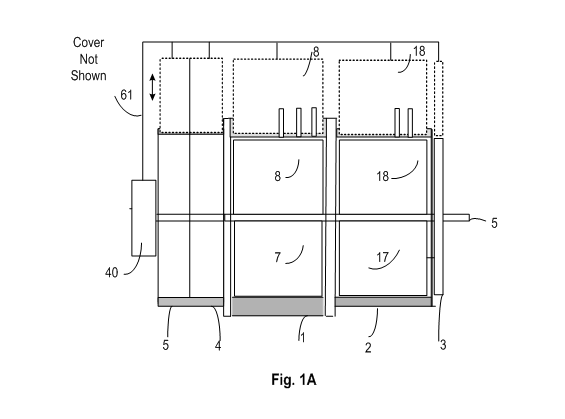
- Figure 1A: is the embodiment of a complete Circular Rotary Turbo Internal Combustion Engine illustrating air, water, oil, gas suction compression pumps,
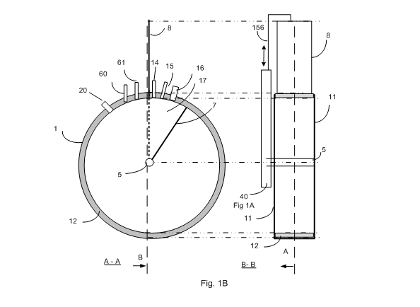
- Figure 1B: is the first embodiment of the Circular Rotary Turbo Internal Combustion Engine.
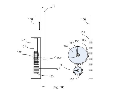
- Figure 1C: is the schematic of gear and timing assembly for the first embodiment of the engine.
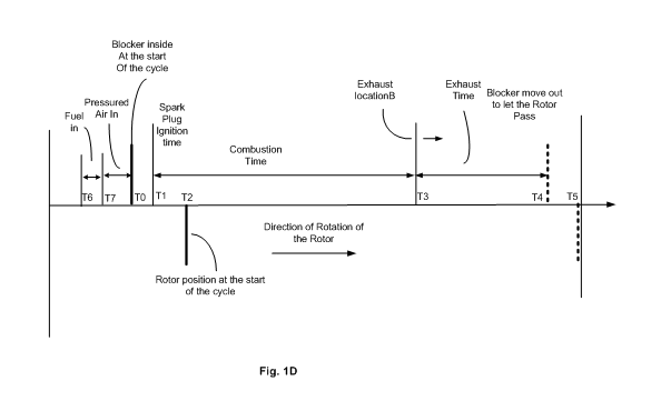
- Figure 1D: is the schematic of timing of the gear assembly for the activation of Blocker with respect to the Rotor.
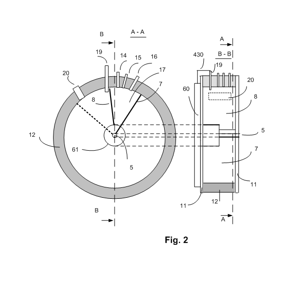
- Figure 2: is the second embodiment of the Circular Rotary Turbo Internal Combustion Engine in which the Blocker rotates alongside the Rotor in the cavity and makes appropriate timely stops during the combustion.
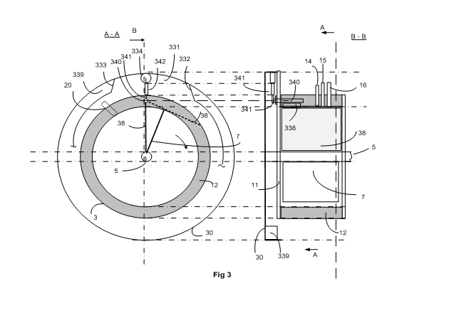
- Figure 3: is the third embodiment of the Engine Circular Rotary Turbo Internal Combustion in which the Blocker is a butterfly shape blade moving in and out of the cavity.
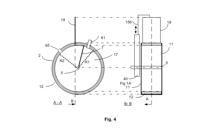
- Figure 4: is the third embodiment of the Circular Rotary single cycle suction and compression pump.
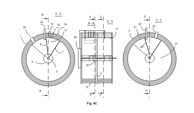
- Figure 4C: is the schematic of the second embodiment of the Circular Rotary Turbo Internal Combustion Engine including the single cycle air pump.
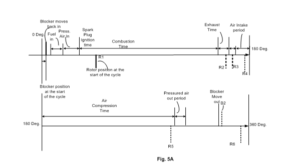
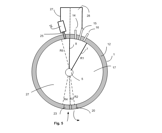
- Figure 5: is the fourth embodiment of the Circular Rotary Turbo Internal Combustion Engine for single cycle compression and combustion in a cavity.
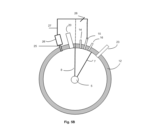
- Figure 5B: is the fifth embodiment of the Circular Rotary Turbo Internal Combustion engine for two cycle compression and combustion in a cavity.
Advantages of the Invention
The invention differs from most of the previous art of internal combustion engine in which the combustion chambers expand radially. The expansion of combustion chamber is between a blade like Rotor that is directly attached to the shaft and extended outward towards the inner surface of the cylinder. The combustion chamber is formed between a blade like Rotor attached to a shaft and a blade like Blocker, making temporary transitional motions to form a barrier and form a combustion chamber. During the combustion time, the Blocker remains stable and the Rotor rotates radially forcing the shaft to move with it.
This new technology in engines provides radical difference compared to the Wankel rotary engine and piston and cylinder engines.
- The Wankel’s rotation of the triangular shape Rotor, is in an elliptical housing and the center of rotation consists of a set of gears to guide the motion in an elliptical cavity. In addition, the most recent patents of so called rotary engines, a reciprocating piston and cylinder configurations is used for combustion chamber and expansion of ignited gas.
- The Wankel engine housing for the generation of pressured air and combustion of pressured air and gas is elliptical. Elliptical housing for the rotor is one of the sources of problems including the frictions between the housing and the Rotor.
- In order for the elliptical motions to take place, the shaft is connected to series of gears to enable elliptical rotation of the Rotor. Generation of elliptical rotation through gear system is the cause and a major contributor of friction.
- The centrifugal force of the rotor in Wankle engine, the variation of tolerances acts as a hammering force destroying the tip of the rotor and the housing.
- By comparison:
- This invention resorts to a circular housing in which the shaft rotates in a center of the circular housing eliminating the requirements of elliptical motions and the necessity of gear system.
- The Rotor is a blade rotating in a spherical or cylindrical housing along the centerline of the housing resulting in minimal deviation in tolerances of the point of contact between the edge of the Rotor and the housing.
- The Blade shape Rotor and the Blocker provides for greater combustion chambers volumes within the cavity compared to Wankel engine’s triangular shape rotor (for the same size volume of an engine). This increase in volume of the combustion, results in greater torque and rotational output power.
- Far smaller number of moving parts allows the engine to be built economically with advantage of greater efficiency in terms of conversion of gas to heat.
- Far lower maintenance cost.
- Different optional implementations for the type of engine allow:
- The air suction / compression to be implemented within the same cavity or external air suction and pump to be implemented in parallel with combustion cavity injecting pressured air before ignition.
- Combinations of air suction and air compression pump provides pressure of air to any desired value for a rich mixture of oxygen, for turbo engine.
- Three different implementation of the Blocker allows for different types of engines with respect to their usages.
- Bigger and more powerful engines will be built by enlarging the volume of the cavity and larger radiuses of the cylindrical shape housing. Multi combustion chambers are done within the same cylindrical cavity for a uniform delivered force.
- In the present piston and said cavity engines, crankshafts occupy a major portion of the engine volumes. They are not gear driven and they operate under heavy load. The crankshafts are the sources of friction and generation of heat that causes engine inefficiency.
- A small timed gear assembly is used to activate the Blocker to let the Rotor to pass for no friction.
- The present engine crankshafts operate under a heavy load. They require constant and heavy cooling and lubrication accessories adding more weight to an engine. Due to far lower frictions and moving parts of this invention, the need for lubrication and cooling are far smaller.
- Due to far less moving parts, friction and heat generations, this invention, allows an air cooling system, that is sufficient for cooling an engine with less moving parts and frictions compared to water cooling, further reducing weight and cost of manufacturing of an engine.
- Crankshaft are build heavy to bear the load for the actual motion of a vehicle. The heaviness adds to the size and weight of an engine.
- This invention provides for a compressed air pump allowing compression of air to any degree desired; by eliminating an open entry air intake side of present turbocharge engines. Due to this open entry of fan like or other presently used compressors.
- The same concept of cavity along with a Rotor and Blocker provides for suction and compression pumps that:
- The suction and compression capability of a pump allows greater freedom in design of engines wherein the source and destination of gas or liquid (to and from the engine) will be irrespective of their locations in the vicinity of the combustion chamber.
Other features and advantages of the present invention will become apparent from the following more detailed description, taken in conjunction with the accompanying drawings, which illustrate, by way of example, the principles of the presently described apparatus and method of its use.
By comparison:
Other features and advantages of the present invention will become apparent from the following more detailed description, taken in conjunction with the accompanying drawings, which illustrate, by way of example, the principles of the presently described apparatus and method of its use.
- This invention resorts to a circular housing in which the shaft rotates in a center of the circular housing eliminating the requirements of elliptical motions and the necessity of gear system.
- The Rotor is a blade rotating in a spherical or cylindrical housing along the centerline of the housing resulting in minimal deviation in tolerances of the point of contact between the edge of the Rotor and the housing.
- Minimal tolerance variations avoids severe loading (pressure) between the edges of the Rotor and the internal walls of the housing, preventing frictions and wear and tear.
- The centrifugal force of the rotor in Wankle engine, the variation of tolerances acts as a hammering force destroying the tip of the rotor and the housing.
- The Blade shape Rotor and the Blocker provides for greater combustion chambers volumes within the cavity compared to Wankel engine’s triangular shape rotor (for the same size volume of an engine). This increase in volume of the combustion, results in greater torque and rotational output power.
- Far smaller number of moving parts allows the engine to be built economically with advantage of greater efficiency in terms of conversion of gas to heat.
- Far lower frictions for eventual higher miles per gallon of gas.
- Far lower maintenance cost.
- Different option implementation for the type of engine allows:
- The design allows for the air compression to be implemented within the same cavity or external air suction and pump to be implemented in parallel with combustion cavity injecting pressured air before ignition.
- Combinations of air suction and air compression pump provides a rich mixture of oxygen for powerful turbo engine.
- Three different implementation of the Blocker allows for different types of engines with respect to their usages.
- Turbochargers and superchargers are fans that force compressed air into an engine’s said cavities. Fans in this case are always open at the air intake side and thus will not produce a high pressure compressed air. That is why they are huge for race car engines.
- Bigger and more powerful engines will be built by enlarging the volume of the cavity and larger radiuses of the cylindrical shape housing. This will eliminate the need for multi piston and cylinders, reducing the number of moving parts and manufacturing costs.
- In the present piston and said cavity engines, crankshafts occupy a major portion of the engine volumes. They are not gear driven and they operate under heavy load. The crankshafts are the sources of friction and generation of heat for eventual failure. This invention does not require crankshaft. A small timed gear assembly is used to activate the Blocker to let the Rotor to pass for no friction.
- The present engine crankshafts operate under a heavy load. They require constant and heavy cooling and lubrication accessories adding more weight to an engine. Due to far lower frictions and moving parts of this invention, the need for lubrication and cooling are far smaller.
- Due to far less moving parts, friction and heat generations, this invention, allows an air cooling system, that is sufficient for cooling an engine with less moving parts and frictions compared to water cooling, further reducing weight and cost of manufacturing of an engine.
- Crankshaft are build heavy to bear the load for the actual motion of a vehicle. The heaviness adds to the size and weight of an engine. The present invention provides for a blade like Rotor and Blocker in which the size and weight are insignificant compared to a crankshaft.
- This invention provides for a dual cycle compressed air pump eliminating an open end air intake side of present turbocharge engines. The same concept of cavity along with a Rotor and Blocker provides for suction and compression pumps that:
- Most turbocharged engines us an oversized open end fan to force pressure air into the combustion chamber.
Other features and advantages of the present invention will become apparent from the following more detailed description, taken in conjunction with the accompanying drawings, which illustrate, by way of example, the principles of the presently described apparatus and method of its use.
Detailed Description of the Invention
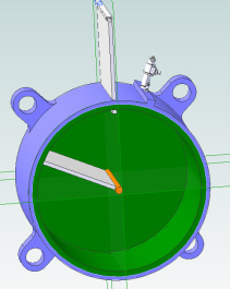
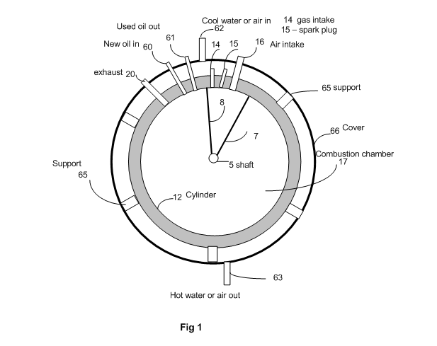
Referring now to Figure 1, for the description of first embodiment of a circular rotary turbo internal combustion cavity with an in out motion of the Blocker. It depicts a cylinder housing (12) with a shaft (5) along the centerline of the cylinder. Shaft (5) rotates in the linear center of the cylinder (12). Attached to the shaft (5) is a Rotor (7), rotating radially with the shaft. A semi stationary Blocker blade (8), getting inserted in and out of the cylinder through a slot in the body of the housing. Blocker blade (8) driven in and out by a gear assembly (40) that is situated outside the cylinder in parallel with the face and covering of the cylinder (11). Attached to the said cavity are fuel injection valve (14) air injection valve (15) spark plug (16) and fuel exhaust (20). The gear assembly (40) is synchronized to the shaft (5), forcing timed insertion, and retraction of the Blocker blade (8) inside the cylinder housing (12).
A variable volume combustion chamber (17) is formed between the Blocker blade (8) and the Rotor (7). At the start of a combustion cycle, powdered fuel (14) and pressured air (15) is injected directly into the compression chamber (17) and then the spark plug (16) introduces and electrical spark to ignite the mixture. During the ignition, while the Blocker is inside the said cavity, the blast forces the Rotor (7) forward, while the Blocker (8) is stationary inside the housing (12). The forced rotation of shaft (5) continues until the ignited fuel is escaped from the exhaust (20). At the moment of ignition, the combustion chamber is small and is filled with mixture of pressured air and fuel. The ignition forces the Rotor (7) forward, rotating the shaft and thus provide rotational power for motion of a vehicle. The fuel injection valve (14) and spark plug (16), each located at proper phase with respect to the rotation of the shaft (5). At the end of the combustion expansion, the exhaust opening (20) lets the exhaust fuels out and the Blocker blade is retracted to let the Rotor (7) to pass.
The combustion chamber (1) is covered by the housing (66) in which the support studs (65), supports the said cavity inside the housing. Attached to the housing cover are provisions to let cold water / air in (61) and cold water / air out (63). The Other connections to the housing are clean oil in (60), used oil out (61)
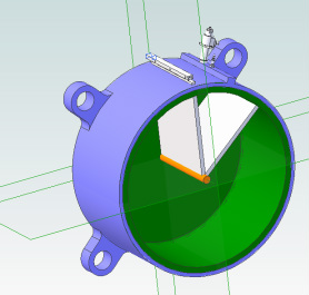
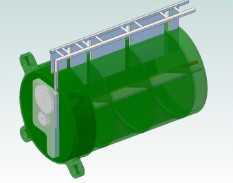
Referring now to Fig. 1B for the description of the complete circular rotary internal combustion engine consisting of combustion chamber (1), air pump (2), fuel pump (3), water pump (4) and oil pump (5), which are all driven by the shaft (5).
Embodiment 1
Referring now to Figure 1B for the description of a circular turbo rotary internal combustion engine (1). It depicts a housing (12 for the cavity, with the center of the rotation of the shaft (5) rotates in the center of said cavity housing (12). Attached to the shaft (5) is a Rotor (7), rotating radially with the shaft. A semi stationary Blocker blade (18), getting inserted in the said cavity through an slot with the face of the blade (18) in parallel with the centerline of shaft (5) driven by a gear assembly (40) that is situated outside the said cavity in parallel with the face of the said cavity (11). Attached to the said cavity are fuel injection valve (14) air injection valve (15) Spark plug (16) and fuel exhaust (20). The gear assembly (40) is driven by the shaft 5, forcing timed insertion, and retraction of the Blocker blade (8) inside the said cavity housing (12).
A variable volume combustion chamber (17) is formed between the Blocker blade (8) and the Rotor (7). At the start of a combustion cycle, powdered fuel (14) and pressured air (15) is injected directly into the compression chamber (17) and then the spark plug (16) introduces and electrical spark to ignite the mixture. During the ignition, while the Blocker is inside the said cavity, the blast forces the Rotor forward, while the Blocker is stationary inside said cavity housing (12). The forced rotation of shaft (5) continues until the ignited fuel is escaped from the exhaust (20). At the moment of ignition, the combustion chamber is small and is filled with mixture of pressured air and fuel. The ignition forces the rotor forward, rotating the shaft and thus provide rotational power for motion of a vehicle. The fuel injection valve (14) and spark plug (16), each located at proper phase with respect to the rotation of the shaft (5). At the end of the combustion expansion, the exhaust opening (20) lets the exhaust fuels out and the Blocker blade is retracted to let the Rotor (7) to rotate.
Referring now to Figure 1C that shows the gear assembly (40) attached to the side of the cylinder covering (11). The timed gear assembly is a rack and pinion type for converting circular motion to linear motion for insertion and extraction of the Blocker (8) from the cylinder. It is consisting of gears (153), (152), a blade like device with groves (151) and a spring (158) to provide the Blocker blade’s (8) reciprocating motions. Gear (153) is attached to the shaft (5) and rotates with it. A larger gear (152) centrally connected to the engine said cavity cover (11) is rotated by gear (153). Gear (152) is partially covered by teeth (159) for the teeth to retract the Blocker blade (8) from cylinder housing (12). For the angle in which gear (152) is without teeth, the two gears are not in contact and the spring (158) forces the gear (152) back to the original position of insertion into the cylinder ready for the next combustion cycle.
Referring now to the Figure 1D, which is the timing diagram of the motions of the Rotor and Insertion Blocker. The details are explained within the diagram which is self-explanatory.
Embodiment 2
Referring now to Figure 2 for the second embodiment of the circular turbo internal combustion engine, which is similar to Figure 1B. It consists of a cylinder shape housing (12), wherein the center of the rotation of the shaft (5) rotates in the center of cylinder housing (12). Attached to the shaft (5) is a blade like Rotor (7), rotating radially with the shaft. A semi stationary rotational Blocker blade (8) attached to tube like device, second shaft (61) that is driven by (60), rotating freely with respect to the shaft (5) and driven by a gear assembly (60) that is situated outside the cylinder in parallel with the area of the cylinder. Attached to the cylinder are fuel injection valve (14) air injection valve (15) Spark plug (16) and fuel exhaust (20). The gear assembly (60) is driven by the shaft (5), forcing timed radial motion of a Blocker (8) inside the cylinder housing (12).
A variable volume combustion chamber (17) is formed between the Blocker (8) and rotor (7). At the start of a combustion cycle, powdered fuel (14) and pressured air(15) in introduced to the compression chamber (17) and then the spark plug (16) introduces and electrical spark to ignite the mixture. During the ignition, the blast forces the Rotor forward while the Blocker is stationary until the ignited fuel is escaped from the exhaust (20). In the remaining time of the complete cycle, the Blocker moves with faster speed behind the Rotor to get stopped again by the stopped pin (19). The Blocker (8) always trails the rotor (7) to get stopped after the stop pin (19) is inserted into the cylinder. The Rotor passes the stop pin (19) while the stop pin is pulled out and then the Blocker is stopped by the stop pin (19) driven by timer gear assemble (60). At the moment of ignition, the combustion chamber is small and is filled with mixture of pressured air and fuel. The ignition forces the rotor forward, rotating the shaft and thus provide rotational power for motion of a vehicle. The fuel injection valve (14) and spark plug (16), each located at proper phase with respect to the rotation of the shaft (5). At the end of the combustion expansion, the exhaust opening (20) lets the exhaust fuels out.
Referring now to Figure 2A, for the description of the timed gear assembly (60) for the second embodiment. The shaft (5) is extended from the combustion engine (1) and is connected to the large gear (21). Gear (21) activates three other gears (211), (212) and (213) respectively. Gear (213) is connected to a second shaft (61) that centrally rotates around the main shaft (5). The second shaft (61) is connected to the Blocker (8) to provide its motions with proper speeds (that is faster than the speed of the Rotor (5)). Gears (212) and (211) are centrally attached and rotate with respect to the stationary engine block (22) that supports their rotations with ball bearings (221) and (222).
Referring now to Figure 2B for the description of the timed stoppage assembly, in which a small hump (219) is attached on top of the large gear (21) for activation of the stoppage rod (230). The position of the hump (219) on the large gear is adjusted to retract the stoppage pin (19), from the cylinder for the Rotor to pass. A ball bearing (234) that is attached to the rod (230), allows the rod to insert and retract the stoppage pin (19) in the combustion chamber (17). A spring (233) with one side connected to the rod (230) via (322) and the other side connected to the engine block (22) via (321) will further guide the motions.
Referring now to Figure 2C, for description of relative timings of the Rotor (7), Blocker (8), and Stoppage pin (19) relative to the shaft (5). It is important to remember that the Rotor is constantly moving and the Blocker is stationary at one location for approximately 270 degrees of the motions of the Rotor. It start moving (behind the Rotor), during the 90 degree remaining time from the stoppage position, for it to get in stop position again. During the 90 degree time period, the stoppage pin retracts to let the Rotor and the Blocker to pass and start the cycle again. The timing Figure 3C shows the rotations of the Rotor, stationary position of Blocker, injection of fuel, injection of the pressured air and ignition by the spark plug. For reference, the end of the period in which the pressured air is injected into the ignition chamber (the area between the Blocker and the rotor (17), is set as T0.
Embodiment 3
Referring now to Figure 3, for the third embodiment of the circular turbo rotary internal combustion engine (1) for a butterfly Blocker method. It depicts a cylinder shape housing (12), with the shaft (5) centrally rotates in the center of cylinder housing (12). Attached to the shaft (5) is a Rotor (7), rotating radially with the shaft. A semi stationary butterfly Blocker (38) getting circularly inserted in the cylinder (for the duration of the time that combustion is taking place and retracted to let the Rotor pass), through the housing of the cylinder housing (12), or a small housing attached to (12). The center line of rotation of the butterfly Blocker is in parallel with the shaft (5). The butterfly Blocker (38) IS driven by a gear assembly external to the cylinder housing (12). Attached to the cylinder are fuel injection valve (14) air injection valve (15) Spark plug (16) and fuel exhaust (20). The gear assembly is driven by the shaft 5, forcing timed insertion, and retraction of the butterfly Blocker blade (38) inside the cylinder housing (12).
A variable volume combustion chamber (17) is formed between the Blocker blade (38) and rotor (7). At the start of a combustion cycle, powdered fuel (14) and pressured air (15) is injected to the compression chamber (17) and then the spark plug (16) introduces and electrical spark to ignite the mixture. During the ignition, while the Blocker is inside the cylinder, the blast forces the Rotor forward while the Blocker is stationary until the ignited fuel is escaped from the exhaust (20). At the moment of ignition, the combustion chamber is small and is filled with mixture of pressured air and fuel. The ignition forces the rotor forward, rotating the shaft and thus provide rotational power for motion of a vehicle. The fuel injection valve (14) and spark plug (16), each located at proper phase with respect to the rotation of the shaft (5). At the end of the combustion expansion, the exhaust opening (20) lets the exhaust fuels out and the Blocker blade is retracted to let the Rotor (7) to rotate.
Attached to the side of the cylinder housing (12) is provisions of the gear assembly Figure 3A for the butterfly Blocker. A circular plate (30) attached to the shaft (5) rotates with the shaft outside cylinder housing (12). The butterfly Blocker is attached to the cylinder housing (12) (or a small housing connected to (12)), with the center of rotation at (340) in which the line of rotation is in parallel with the shaft (5).
Referring now to Fig 3A, when the round plate (30) rotates, its edges are equipped with two segments of (331) and (339). Segment (339) is a round edged semi-circle band in which the outside radius of the band has the same radios of plate (30) and the inside radios of the band is smaller than outer radius. When the plate (30) rotates, the ball bearing (334) makes contact with outer radius of (30) edges or with the inner radius of the band (339). Band (331) is for the portion of the cycle time in which the butterfly Blocker needs to be in closed state inside the cylinder, and no contact during the portion of the cycle time (331). A spring (342) connected to the rod (341) will force the ball bearing (334) to be in contact with either (331) OR (339). When a ball bearing (334) passes near the edge of the band (332), it inserts the butterfly Blocker (38) inside the cylinder and keeps it there till it reaches the edge (333), in which the Blocker (38) is retracted to the side of the cylinder to let the Rotor pass. During the (331) cycle timing a spring (337) forces the rod (340) to get the butterfly Blocker out of the cylinder housing (12) roe the Rotor (7) to pass.
Referring now to Figure 1, for the description of first embodiment of a circular rotary turbo internal combustion cavity with an in out motion of the Blocker. It depicts a cylinder housing (12) with a shaft (5) along the centerline of the cylinder. Shaft (5) rotates in the linear center of the cylinder (12). Attached to the shaft (5) is a Rotor (7), rotating radially with the shaft. A semi stationary Blocker blade (8), getting inserted in and out of the cylinder through a slot in the body of the housing. Blocker blade (8) driven in and out by a gear assembly (40) that is situated outside the cylinder in parallel with the face and covering of the cylinder (11). Attached to the said cavity are fuel injection valve (14) air injection valve (15) spark plug (16) and fuel exhaust (20). The gear assembly (40) is synchronized to the shaft (5), forcing timed insertion, and retraction of the Blocker blade (8) inside the cylinder housing (12).
A variable volume combustion chamber (17) is formed between the Blocker blade (8) and the Rotor (7). At the start of a combustion cycle, powdered fuel (14) and pressured air (15) is injected directly into the compression chamber (17) and then the spark plug (16) introduces and electrical spark to ignite the mixture. During the ignition, while the Blocker is inside the said cavity, the blast forces the Rotor (7) forward, while the Blocker (8) is stationary inside the housing (12). The forced rotation of shaft (5) continues until the ignited fuel is escaped from the exhaust (20). At the moment of ignition, the combustion chamber is small and is filled with mixture of pressured air and fuel. The ignition forces the Rotor (7) forward, rotating the shaft and thus provide rotational power for motion of a vehicle. The fuel injection valve (14) and spark plug (16), each located at proper phase with respect to the rotation of the shaft (5). At the end of the combustion expansion, the exhaust opening (20) lets the exhaust fuels out and the Blocker blade is retracted to let the Rotor (7) to pass.
The combustion chamber (1) is covered by the housing (66) in which the support studs (65), supports the said cavity inside the housing. Attached to the housing cover are provisions to let cold water / air in (61) and cold water / air out (63). The Other connections to the housing are clean oil in (60), used oil out (61)
Referring now to Fig. 1B for the description of the complete circular rotary internal combustion engine consisting of combustion chamber (1), air pump (2), fuel pump (3), water pump (4) and oil pump (5), which are all driven by the shaft (5).
Embodiment 1
Referring now to Figure 1B for the description of a circular turbo rotary internal combustion engine (1). It depicts a housing (12 for the cavity, with the center of the rotation of the shaft (5) rotates in the center of said cavity housing (12). Attached to the shaft (5) is a Rotor (7), rotating radially with the shaft. A semi stationary Blocker blade (18), getting inserted in the said cavity through an slot with the face of the blade (18) in parallel with the centerline of shaft (5) driven by a gear assembly (40) that is situated outside the said cavity in parallel with the face of the said cavity (11). Attached to the said cavity are fuel injection valve (14) air injection valve (15) Spark plug (16) and fuel exhaust (20). The gear assembly (40) is driven by the shaft 5, forcing timed insertion, and retraction of the Blocker blade (8) inside the said cavity housing (12).
A variable volume combustion chamber (17) is formed between the Blocker blade (8) and the Rotor (7). At the start of a combustion cycle, powdered fuel (14) and pressured air (15) is injected directly into the compression chamber (17) and then the spark plug (16) introduces and electrical spark to ignite the mixture. During the ignition, while the Blocker is inside the said cavity, the blast forces the Rotor forward, while the Blocker is stationary inside said cavity housing (12). The forced rotation of shaft (5) continues until the ignited fuel is escaped from the exhaust (20). At the moment of ignition, the combustion chamber is small and is filled with mixture of pressured air and fuel. The ignition forces the rotor forward, rotating the shaft and thus provide rotational power for motion of a vehicle. The fuel injection valve (14) and spark plug (16), each located at proper phase with respect to the rotation of the shaft (5). At the end of the combustion expansion, the exhaust opening (20) lets the exhaust fuels out and the Blocker blade is retracted to let the Rotor (7) to rotate.
Referring now to Figure 1C that shows the gear assembly (40) attached to the side of the cylinder covering (11). The timed gear assembly is a rack and pinion type for converting circular motion to linear motion for insertion and extraction of the Blocker (8) from the cylinder. It is consisting of gears (153), (152), a blade like device with groves (151) and a spring (158) to provide the Blocker blade’s (8) reciprocating motions. Gear (153) is attached to the shaft (5) and rotates with it. A larger gear (152) centrally connected to the engine said cavity cover (11) is rotated by gear (153). Gear (152) is partially covered by teeth (159) for the teeth to retract the Blocker blade (8) from cylinder housing (12). For the angle in which gear (152) is without teeth, the two gears are not in contact and the spring (158) forces the gear (152) back to the original position of insertion into the cylinder ready for the next combustion cycle.
Referring now to the Figure 1D, which is the timing diagram of the motions of the Rotor and Insertion Blocker. The details are explained within the diagram which is self-explanatory.
Embodiment 2
Referring now to Figure 2 for the second embodiment of the circular turbo internal combustion engine, which is similar to Figure 1B. It consists of a cylinder shape housing (12), wherein the center of the rotation of the shaft (5) rotates in the center of cylinder housing (12). Attached to the shaft (5) is a blade like Rotor (7), rotating radially with the shaft. A semi stationary rotational Blocker blade (8) attached to tube like device, second shaft (61) that is driven by (60), rotating freely with respect to the shaft (5) and driven by a gear assembly (60) that is situated outside the cylinder in parallel with the area of the cylinder. Attached to the cylinder are fuel injection valve (14) air injection valve (15) Spark plug (16) and fuel exhaust (20). The gear assembly (60) is driven by the shaft (5), forcing timed radial motion of a Blocker (8) inside the cylinder housing (12).
A variable volume combustion chamber (17) is formed between the Blocker (8) and rotor (7). At the start of a combustion cycle, powdered fuel (14) and pressured air(15) in introduced to the compression chamber (17) and then the spark plug (16) introduces and electrical spark to ignite the mixture. During the ignition, the blast forces the Rotor forward while the Blocker is stationary until the ignited fuel is escaped from the exhaust (20). In the remaining time of the complete cycle, the Blocker moves with faster speed behind the Rotor to get stopped again by the stopped pin (19). The Blocker (8) always trails the rotor (7) to get stopped after the stop pin (19) is inserted into the cylinder. The Rotor passes the stop pin (19) while the stop pin is pulled out and then the Blocker is stopped by the stop pin (19) driven by timer gear assemble (60). At the moment of ignition, the combustion chamber is small and is filled with mixture of pressured air and fuel. The ignition forces the rotor forward, rotating the shaft and thus provide rotational power for motion of a vehicle. The fuel injection valve (14) and spark plug (16), each located at proper phase with respect to the rotation of the shaft (5). At the end of the combustion expansion, the exhaust opening (20) lets the exhaust fuels out.
Referring now to Figure 2A, for the description of the timed gear assembly (60) for the second embodiment. The shaft (5) is extended from the combustion engine (1) and is connected to the large gear (21). Gear (21) activates three other gears (211), (212) and (213) respectively. Gear (213) is connected to a second shaft (61) that centrally rotates around the main shaft (5). The second shaft (61) is connected to the Blocker (8) to provide its motions with proper speeds (that is faster than the speed of the Rotor (5)). Gears (212) and (211) are centrally attached and rotate with respect to the stationary engine block (22) that supports their rotations with ball bearings (221) and (222).
Referring now to Figure 2B for the description of the timed stoppage assembly, in which a small hump (219) is attached on top of the large gear (21) for activation of the stoppage rod (230). The position of the hump (219) on the large gear is adjusted to retract the stoppage pin (19), from the cylinder for the Rotor to pass. A ball bearing (234) that is attached to the rod (230), allows the rod to insert and retract the stoppage pin (19) in the combustion chamber (17). A spring (233) with one side connected to the rod (230) via (322) and the other side connected to the engine block (22) via (321) will further guide the motions.
Referring now to Figure 2C, for description of relative timings of the Rotor (7), Blocker (8), and Stoppage pin (19) relative to the shaft (5). It is important to remember that the Rotor is constantly moving and the Blocker is stationary at one location for approximately 270 degrees of the motions of the Rotor. It start moving (behind the Rotor), during the 90 degree remaining time from the stoppage position, for it to get in stop position again. During the 90 degree time period, the stoppage pin retracts to let the Rotor and the Blocker to pass and start the cycle again. The timing Figure 3C shows the rotations of the Rotor, stationary position of Blocker, injection of fuel, injection of the pressured air and ignition by the spark plug. For reference, the end of the period in which the pressured air is injected into the ignition chamber (the area between the Blocker and the rotor (17), is set as T0.
Embodiment 3
Referring now to Figure 3, for the third embodiment of the circular turbo rotary internal combustion engine (1) for a butterfly Blocker method. It depicts a cylinder shape housing (12), with the shaft (5) centrally rotates in the center of cylinder housing (12). Attached to the shaft (5) is a Rotor (7), rotating radially with the shaft. A semi stationary butterfly Blocker (38) getting circularly inserted in the cylinder (for the duration of the time that combustion is taking place and retracted to let the Rotor pass), through the housing of the cylinder housing (12), or a small housing attached to (12). The center line of rotation of the butterfly Blocker is in parallel with the shaft (5). The butterfly Blocker (38) IS driven by a gear assembly external to the cylinder housing (12). Attached to the cylinder are fuel injection valve (14) air injection valve (15) Spark plug (16) and fuel exhaust (20). The gear assembly is driven by the shaft 5, forcing timed insertion, and retraction of the butterfly Blocker blade (38) inside the cylinder housing (12).
A variable volume combustion chamber (17) is formed between the Blocker blade (38) and rotor (7). At the start of a combustion cycle, powdered fuel (14) and pressured air (15) is injected to the compression chamber (17) and then the spark plug (16) introduces and electrical spark to ignite the mixture. During the ignition, while the Blocker is inside the cylinder, the blast forces the Rotor forward while the Blocker is stationary until the ignited fuel is escaped from the exhaust (20). At the moment of ignition, the combustion chamber is small and is filled with mixture of pressured air and fuel. The ignition forces the rotor forward, rotating the shaft and thus provide rotational power for motion of a vehicle. The fuel injection valve (14) and spark plug (16), each located at proper phase with respect to the rotation of the shaft (5). At the end of the combustion expansion, the exhaust opening (20) lets the exhaust fuels out and the Blocker blade is retracted to let the Rotor (7) to rotate.
Attached to the side of the cylinder housing (12) is provisions of the gear assembly Figure 3A for the butterfly Blocker. A circular plate (30) attached to the shaft (5) rotates with the shaft outside cylinder housing (12). The butterfly Blocker is attached to the cylinder housing (12) (or a small housing connected to (12)), with the center of rotation at (340) in which the line of rotation is in parallel with the shaft (5).
Referring now to Fig 3A, when the round plate (30) rotates, its edges are equipped with two segments of (331) and (339). Segment (339) is a round edged semi-circle band in which the outside radius of the band has the same radios of plate (30) and the inside radios of the band is smaller than outer radius. When the plate (30) rotates, the ball bearing (334) makes contact with outer radius of (30) edges or with the inner radius of the band (339). Band (331) is for the portion of the cycle time in which the butterfly Blocker needs to be in closed state inside the cylinder, and no contact during the portion of the cycle time (331). A spring (342) connected to the rod (341) will force the ball bearing (334) to be in contact with either (331) OR (339). When a ball bearing (334) passes near the edge of the band (332), it inserts the butterfly Blocker (38) inside the cylinder and keeps it there till it reaches the edge (333), in which the Blocker (38) is retracted to the side of the cylinder to let the Rotor pass. During the (331) cycle timing a spring (337) forces the rod (340) to get the butterfly Blocker out of the cylinder housing (12) roe the Rotor (7) to pass.
Circular Rotary Pumps
This invention provides for a compression of air pump making possible compression of air to any degree desired. Certain volume of ambient air is sucked into a pressure chamber, allowing pressurization of the air. A vacuum inside the compression chamber is created, to dynamically force the air inside the chamber. Upon closure of the pressure chamber, the trapped air is then pressurized in which pressurization take place by reduction of the volume circularly. This pump is energized electrically or by fossil fuel. The suction and compression capability of this pump allows greater freedom in design of pumps;
- Pumps will no longer have to be immersed in the gas, water or sewage systems to pump liquids.
- The pump is built much less expensive, greater efficiency, and lower costs of maintenances.
- This concept of suction and compression of liquids allows insertion of a pipe into liquids stored below ground, eliminating the need for immersed pumps.
Circular Rotary Turbo Interbal Combustion Engine

|
|
