
Circular rotary turbo interbal combustion engine
Inventor
Ned M. Ahdoot Patent Pending No. 13/987,425
Ned M. Ahdoot Patent Pending No. 13/987,425
|
|
|
BRIEF SUMMARY OF THE INVENTION
The engine consists of a cylinder that is formed by a spherical or cylindrical housing (12). A Rotor (7) attached to a shaft (5), centrally rotating inside the cylinder along the center line of the rotation of the cylinder. A combustion chamber (17) is formed inside the cylinder by a blade like Blocker (8) and a blade like Rotor in which ignition takes place, and the ignition chamber expands radially providing rotational power to the shaft.
The engine consists of a cylinder that is formed by a spherical or cylindrical housing (12). A Rotor (7) attached to a shaft (5), centrally rotating inside the cylinder along the center line of the rotation of the cylinder. A combustion chamber (17) is formed inside the cylinder by a blade like Blocker (8) and a blade like Rotor in which ignition takes place, and the ignition chamber expands radially providing rotational power to the shaft.
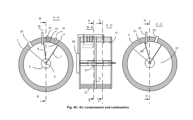
Figure 4C- Is the combination of the Combustion chamber (17) and the Compression chamber (27) in which the air is compressed by initial suction of the air into the Compression chamber and rotation of the Combustion Rotor attached to the same shaft (5).
Brief description of Figures
Advantages of the Invention
The invention differs from most of the previous art internal combustion engine in which the combustion chambers expand radially Unlike the present art, this invention provides expansion of combustion chamber between a blade like Rotor that is directly attached to the shaft and extended outward towards the inner surface of the housing of a cavity, and radially rotating inside the cavity. A combustion chamber is formed between a Rotor attached to a shaft and a blade like Blocker, making temporary transitional motions to form a barrier inside the cavity and form a combustion chamber. The combustion chamber is formed between the Blocker and the Rotor during combustion time, the Blocker remains stable and the Rotor rotates radially forcing the shaft to move with it.
This is a radical difference between the original Wankel rotary engine. The Wankel’s rotation of the Rotor is in an elliptical housing and the center of rotation consists of a set of gears to guide the motion in a elliptical cavity. In the most recent patents of so called rotary engines, a reciprocating piston and cylinder configurations is used for combustion chamber and expansion of ignited gas. The Wankel engine housing for the generation of pressured air and combustion of pressured air and gas is elliptical. Elliptical housing for the rotor is one of the sources of problems including the frictions between the housing and the rotor. In order for the elliptical motions to take place, the shaft is connected to series of gears for the elliptical rotations. Generation of elliptical rotation through gear system is the cause and a major contributor of friction.
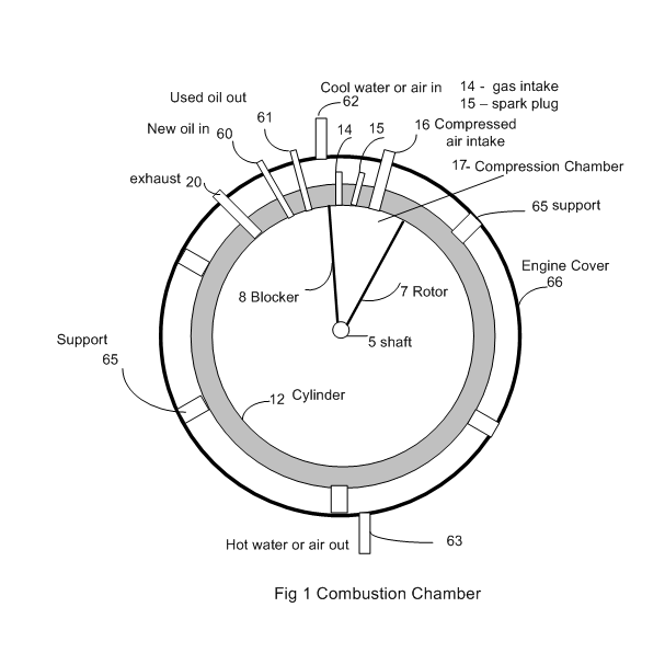
- Figure 1: is the embodiment of the Circular Rotary Turbo Internal Combustion Engine including the cylindrical housing and the cover of the engine.
- Figure 4C: is the embodiment of a complete Circular Rotary Turbo Internal Combustion Engine illustrating air, water, oil, gas suction compression pumps,
- Figure 2A: is the schematic of gear and timing assembly for the second embodiment of the engine.
- Figure 2B: is the schematic of method of activating the Blocker for the second embodiment of the engine.
- Figure 2C: is the schematic of timing of the gear assembly for the activation of Blocker with respect to Rotor.
- Figure 5: is the fourth embodiment of the Circular Rotary Turbo Internal Combustion Engine for single cycle compression and combustion in a cylinder.
- Figure 5A: is the schematic of timing for gear assembly for the fourth embodiment of the engine.
- Figure 5B: is the fifth embodiment of the Circular Rotary Turbo Internal Combustion engine for two cycle compression and combustion in a cylinder.
- Figure 6: is the timing schematic of a two cycle suction and compression for the circular suction and compression, one cycle for suction and another cycle for compression.
- Figure 6B: is a schematic of single cycle suction and compression pumps utilizing the timed gear assembly timing reciprocating motions for a single cycle air compression and suction.
Advantages of the Invention
The invention differs from most of the previous art internal combustion engine in which the combustion chambers expand radially Unlike the present art, this invention provides expansion of combustion chamber between a blade like Rotor that is directly attached to the shaft and extended outward towards the inner surface of the housing of a cavity, and radially rotating inside the cavity. A combustion chamber is formed between a Rotor attached to a shaft and a blade like Blocker, making temporary transitional motions to form a barrier inside the cavity and form a combustion chamber. The combustion chamber is formed between the Blocker and the Rotor during combustion time, the Blocker remains stable and the Rotor rotates radially forcing the shaft to move with it.
This is a radical difference between the original Wankel rotary engine. The Wankel’s rotation of the Rotor is in an elliptical housing and the center of rotation consists of a set of gears to guide the motion in a elliptical cavity. In the most recent patents of so called rotary engines, a reciprocating piston and cylinder configurations is used for combustion chamber and expansion of ignited gas. The Wankel engine housing for the generation of pressured air and combustion of pressured air and gas is elliptical. Elliptical housing for the rotor is one of the sources of problems including the frictions between the housing and the rotor. In order for the elliptical motions to take place, the shaft is connected to series of gears for the elliptical rotations. Generation of elliptical rotation through gear system is the cause and a major contributor of friction.
Brief description of Figures
Advantages of the Invention
The invention differs from most of the previous art internal combustion engine in which the combustion chambers expand radially Unlike the present art, this invention provides expansion of combustion chamber between a blade like Rotor that is directly attached to the shaft and extended outward towards the inner surface of the housing of a cylinder, and radially rotating inside the cylinder. A combustion chamber is formed between a Rotor attached to a shaft and a blade like Blocker, making temporary transitional motions to form a barrier inside the cylinder and form a combustion chamber. The combustion chamber is formed between the Blocker and the Rotor during combustion time, the Blocker remains stable and the Rotor rotates radially forcing the shaft to move with it.
This is a radical difference between the original Wankel rotary engine. The Wankel’s rotation of the Rotor is in an elliptical housing and the center of rotation consists of a set of gears to guide the motion in a elliptical cylinder. In the most recent patents of so called rotary engines, a reciprocating piston and cylinder configurations is used for combustion chamber and expansion of ignited gas. The Wankel engine housing for the generation of pressured air and combustion of pressured air and gas is elliptical. Elliptical housing for the rotor is one of the sources of problems including the frictions between the housing and the rotor. In order for the elliptical motions to take place, the shaft is connected to series of gears for the elliptical rotations. Generation of elliptical rotation through gear system is the cause and a major contributor of friction.
By comparison:
Other features and advantages of the present invention will become apparent from the following more detailed description, taken in conjunction with the accompanying drawings, which illustrate, by way of example, the principles of the presently described apparatus and method of its use.
- This invention resorts to a circular housing in which the shaft rotates in a center of the circular housing eliminating the requirements of elliptical motions and the necessity of gear system.
- The Rotor is a blade rotating in a spherical or cylindrical housing along the centerline of the housing resulting in minimal deviation in tolerances of the point of contact between the edge of the Rotor and the housing.
- Minimal tolerance variations avoids severe loading (pressure) between the edges of the Rotor and the internal walls of the housing, preventing frictions and wear and tear.
- The centrifugal force of the rotor in Wankle engine, the variation of tolerances acts as a hammering force destroying the tip of the rotor and the housing.
- The Blade shape Rotor and the Blocker provides for greater combustion chambers volumes within the cavity compared to Wankel engine’s triangular shape rotor (for the same size volume of an engine). This increase in volume of the combustion, results in greater torque and rotational output power.
- Far smaller number of moving parts allows the engine to be built economically with advantage of greater efficiency in terms of conversion of gas to heat.
- Far lower frictions for eventual higher miles per gallon of gas.
- Far lower maintenance cost.
- Different option implementation for the type of engine allows:
- The design allows for the air compression to be implemented within the same cavity or external air suction and pump to be implemented in parallel with combustion cavity injecting pressured air before ignition.
- Combinations of air suction and air compression pump provides a rich mixture of oxygen for powerful turbo engine.
- Three different implementation of the Blocker allows for different types of engines with respect to their usages.
- Turbochargers and superchargers are fans that force compressed air into an engine’s said cavities. Fans in this case are always open at the air intake side and thus will not produce a high pressure compressed air. That is why they are huge for race car engines.
- Bigger and more powerful engines will be built by enlarging the volume of the cavity and larger radiuses of the cylindrical shape housing. This will eliminate the need for multi piston and cylinders, reducing the number of moving parts and manufacturing costs.
- In the present piston and said cavity engines, crankshafts occupy a major portion of the engine volumes. They are not gear driven and they operate under heavy load. The crankshafts are the sources of friction and generation of heat for eventual failure. This invention does not require crankshaft. A small timed gear assembly is used to activate the Blocker to let the Rotor to pass for no friction.
- The present engine crankshafts operate under a heavy load. They require constant and heavy cooling and lubrication accessories adding more weight to an engine. Due to far lower frictions and moving parts of this invention, the need for lubrication and cooling are far smaller.
- Due to far less moving parts, friction and heat generations, this invention, allows an air cooling system, that is sufficient for cooling an engine with less moving parts and frictions compared to water cooling, further reducing weight and cost of manufacturing of an engine.
- Crankshaft are build heavy to bear the load for the actual motion of a vehicle. The heaviness adds to the size and weight of an engine. The present invention provides for a blade like Rotor and Blocker in which the size and weight are insignificant compared to a crankshaft.
- This invention provides for a dual cycle compressed air pump eliminating an open end air intake side of present turbocharge engines. The same concept of cavity along with a Rotor and Blocker provides for suction and compression pumps that:
- Most turbocharged engines us an oversized open end fan to force pressure air into the combustion chamber.
Other features and advantages of the present invention will become apparent from the following more detailed description, taken in conjunction with the accompanying drawings, which illustrate, by way of example, the principles of the presently described apparatus and method of its use.
Detailed Description of the Invention
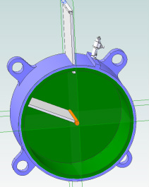
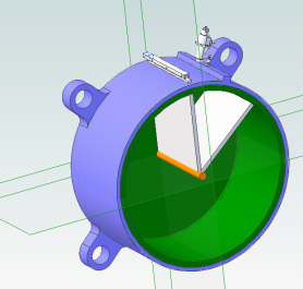
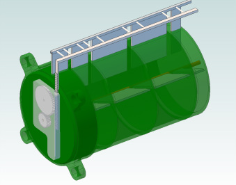
Referring now to Figure 1, for the description of first embodiment of a circular rotary turbo internal combustion cavity with an in out motion of the Blocker. It depicts a cylinder housing (12) with a shaft (5) along the centerline of the cylinder. Shaft (5) rotates in the linear center of the cylinder (12). Attached to the shaft (5) is a Rotor (7), rotating radially with the shaft. A semi stationary Blocker blade (8), getting inserted in and out of the cylinder through a slot in the body of the housing. Blocker blade (8) driven in and out by a gear assembly (40) that is situated outside the cylinder in parallel with the face and covering of the cylinder (11). Attached to the said cavity are fuel injection valve (14) air injection valve (15) spark plug (16) and fuel exhaust (20). The gear assembly (40) is synchronized to the shaft (5), forcing timed insertion, and retraction of the Blocker blade (8) inside the cylinder housing (12).
A variable volume combustion chamber (17) is formed between the Blocker blade (8) and the Rotor (7). At the start of a combustion cycle, powdered fuel (14) and pressured air (15) is injected directly into the compression chamber (17) and then the spark plug (16) introduces and electrical spark to ignite the mixture. During the ignition, while the Blocker is inside the said cavity, the blast forces the Rotor (7) forward, while the Blocker (8) is stationary inside the housing (12). The forced rotation of shaft (5) continues until the ignited fuel is escaped from the exhaust (20). At the moment of ignition, the combustion chamber is small and is filled with mixture of pressured air and fuel. The ignition forces the Rotor (7) forward, rotating the shaft and thus provide rotational power for motion of a vehicle. The fuel injection valve (14) and spark plug (16), each located at proper phase with respect to the rotation of the shaft (5). At the end of the combustion expansion, the exhaust opening (20) lets the exhaust fuels out and the Blocker blade is retracted to let the Rotor (7) to pass.
The combustion chamber (17) is covered by the housing (66) in which the support studs (65), supports the said cavity inside the housing. Attached to the housing cover are provisions to let cold water / air in (61) and cold water / air out (63). The Other connections to the housing are clean oil in (60), used oil out (61)
Referring now to Fig. 1B for the description of the complete circular rotary internal combustion engine consisting of combustion chamber (1), air pump (2), fuel pump (3), water pump (4) and oil pump (5), which are all driven by the shaft (5).
Combustion
A variable volume combustion chamber (17) is formed between the Blocker (8) and rotor (7). At the start of a combustion cycle, powdered fuel (14) and pressured air(15) in introduced to the compression chamber (17) and then the spark plug (16) introduces and electrical spark to ignite the mixture. During the ignition, the blast forces the Rotor forward while the Blocker is stationary until the ignited fuel is escaped from the exhaust (20). In the remaining time of the complete cycle, the Blocker moves with faster speed behind the Rotor to get stopped again by the stopped pin (19). The Blocker (8) always trails the rotor (7) to get stopped after the stop pin (19) is inserted into the cylinder. The Rotor passes the stop pin (19) while the stop pin is pulled out and then the Blocker is stopped by the stop pin (19) driven by timer gear assemble (60). At the moment of ignition, the combustion chamber is small and is filled with mixture of pressured air and fuel. The ignition forces the rotor forward, rotating the shaft and thus provide rotational power for motion of a vehicle. The fuel injection valve (14) and spark plug (16), each located at proper phase with respect to the rotation of the shaft (5). At the end of the combustion expansion, the exhaust opening (20) lets the exhaust fuels out.
A variable volume combustion chamber (17) is formed between the Blocker (8) and rotor (7). At the start of a combustion cycle, powdered fuel (14) and pressured air(15) in introduced to the compression chamber (17) and then the spark plug (16) introduces and electrical spark to ignite the mixture. During the ignition, the blast forces the Rotor forward while the Blocker is stationary until the ignited fuel is escaped from the exhaust (20). In the remaining time of the complete cycle, the Blocker moves with faster speed behind the Rotor to get stopped again by the stopped pin (19). The Blocker (8) always trails the rotor (7) to get stopped after the stop pin (19) is inserted into the cylinder. The Rotor passes the stop pin (19) while the stop pin is pulled out and then the Blocker is stopped by the stop pin (19) driven by timer gear assemble (60). At the moment of ignition, the combustion chamber is small and is filled with mixture of pressured air and fuel. The ignition forces the rotor forward, rotating the shaft and thus provide rotational power for motion of a vehicle. The fuel injection valve (14) and spark plug (16), each located at proper phase with respect to the rotation of the shaft (5). At the end of the combustion expansion, the exhaust opening (20) lets the exhaust fuels out.
